Currently, the industry is immersed in a phase of adopting the trends established by Industry 4.0, characterized as the fourth industrial revolution. This transformation is primarily based on the implementation of various Information Technologies (IT) in the industrial context.
Among these technologies, the following stand out:
1) Automation,
2) Robotisation,
3) Data Analysis (big data),
4) Virtualisation,
5) Artificial Intelligence (AI), and the Internet of Things (IoT).
All these elements converge to improve processes, increase operational efficiency, and promote deeper integration between different systems, which, combined, provide a smarter and more interconnected industrial environment. In these contexts, the digitalisation of processes and products through sensing to obtain data takes on particular importance. The sensing of structures/components and processes is an indispensable factor in the industrial digitalisation process, as it is through sensing that we enable a process or product to obtain data and communicate with its surroundings.
It is through the application of different sensing techniques that the process, or the component/structure itself, acquires the characteristics necessary for monitoring its performance and consequently enhancing the data obtained, in service or production, through the application of different signal processing or data analysis techniques. This is undoubtedly one of the most promising paths to conferring intelligence and interactivity to processes and products. This approach gives these systems the ability to communicate, through interfaces created specifically for different purposes, with the various actors in the production chain or end users. This interconnectivity not only improves operational efficiency but also opens up new possibilities for the customization and dynamic adaptation of products and services to specific market demands. Furthermore, the virtualization of components and processes through numerical simulation techniques, both of the process and the product, plays a crucial role in creating the Digital Twins necessary, for example, for the real-time optimization of production processes, using numerical optimization techniques or applying Artificial Intelligence (AI) methods. Indeed, the integration of experimental (real) data with numerical (virtual) data, along with the improvement of their interrelationship, combined with increased computational power and the greater maturity of numerical methodologies for data processing, creates possibilities for monitoring and controlling the behavior of components, structures, and processes. This convergence unlocks unprecedented possibilities, previously unattainable.
PIEP has been focusing its efforts on implementing digitalisation concepts across the various sectors in which it operates. This article will focus on various case studies, demonstrating and highlighting the potential of the various digitalisation techniques applied by PIEP and the strategy we are adopting in this application context.
Case study 1 – Virtualisation and numerical simulation of the production process
Injection moulding process simulation can be applied during the part and mold design development phase to validate geometries for process applicability, as well as to identify and minimize potential defects. Implementing these advanced strategies in the part and mold development process can reduce costs, optimize mold development efficiency, and streamline the manufacturing and mold testing process, all contributing to a shorter time to market.
By applying advanced injection molding process simulation tools, detailed analyses of polymer behavior and the influence of process conditions can be performed. This approach provides a deeper understanding of critical variables, such as temperature, pressure, and shear rate, applied to the material flow during injection, helping to identify potential causes of defects in the final product.
As a product virtualization technique, 3D scanning has applications in a variety of processes across numerous industries, becoming a key tool in achieving the initially envisioned product. 3D scanning scanners not only stand out as innovative tools in the development process but also play a crucial role in geometric control in factory floor environments. The direct integration of this technology into assembly lines enables real-time information on the quality of assembly and production processes. This capability offers companies the opportunity to make immediate adjustments, aligning quickly and accurately with the dynamic demands of Industry 4.0 (2) (3). This approach improves operational efficiency but also contributes to the implementation of adaptive production practices, enabling instant response to process variations and ensuring consistent quality standards throughout production. The strategic use of 3D scanners as control instruments on the production line represents a significant advance in achieving the principles of Industry 4.0.
In terms of product development, 3D scanning is a tool with high application potential, as it makes the process iterative, more dynamic, and faster (3). One of the most widely used 3D scanning technologies is structured light. This involves projecting a light pattern and capturing the distortions in this pattern due to the geometric characteristics of the surface being scanned. One of the advantages associated with this technique is scanning speed, where the scanner does not capture information point by point, but rather multiple points simultaneously, depending on the scanner’s field of view (3). Another of the most widely used technologies is laser scanning. This involves projecting one or more laser lines onto the sample surface and, through their reflection, capturing its geometry. Although it allows for fast scanning, it is slower than structured light and generally requires special markers for the triangulation process to be established correctly. This triangulation gives this technology better dimensional accuracy than the structured light technique (4) (5).
In this case study, a dimensional analysis of an injected thermoplastic component was performed using a 3D scanner for subsequent comparison with dimensional results obtained through simulation of the production process. After the first versions of the component were produced, shape scans were taken and compared with the CAD model (baseline) of the part to: 1) locate the part’s deformations; 2) correlate them with the values obtained through numerical simulation of the process; and 3) correct the production process, minimizing and/or eliminating the observed warpages.
For the virtual process evaluation, a multi-competence simulation of the injection molding process of a single part was performed during the mold development phase to adapt its geometry and ensure its suitability for the process. The following analyses were performed: 1) analysis of the flow front and profile; 2) identification of short-shots; and 3) analysis of the cooling channel efficiency. In this particular context, considering that the part is part of a system that will be subsequently assembled and the materials are highly loaded, precise control and a detailed dimensional analysis of the component are crucial. The results of this analysis are shown in Figure 1. After the process simulation, which aided in mold development, initial tests were performed, resulting in the injection of parts. Based on these data, a comparative study was performed between the predicted deformation resulting from the simulation and the actual deformation of the part, using 3D scanning technology with the Einscan HX scanner from Shinning 3D, shown in Figure 2. The values obtained are compiled in Table 1. Despite some quantitative differences between the numerical and experimental values, the warpage tendency of the part was adequately predicted by the process simulation. Regarding the difference in displacement values obtained, it should be noted that the location of the points on the digitized model and the probes on the simulation model (representing the points on the actual part) for measuring the distances are approximate, which may contribute to measurement error. However, it was possible to validate that the process simulation can predict the warpage configuration, which is concave in the case of the sidewalls and in the areas of greatest deformation. These results guarantee the ability of process simulation to qualitatively predict the warpage of a part produced by injection molding, being an important tool for the development of design models, definition of the appropriate process conditions window and, in the future, as an auxiliary tool for the real-time suitability of the injection process, in the context of application of the Digital Twin methodology.
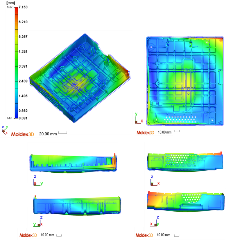
Figure 1 – Deformation of the part, obtained by simulating the injection molding process, using the commercial Moldex3D software.
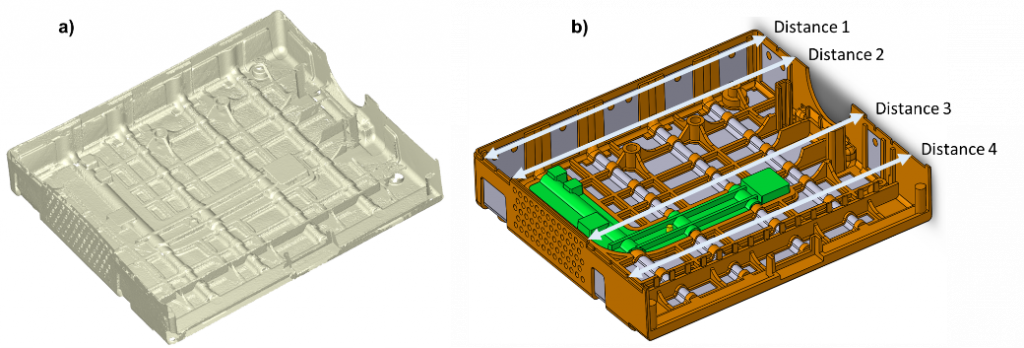
Figure 2 – a) scanned part; b) distances measured in the process simulation.
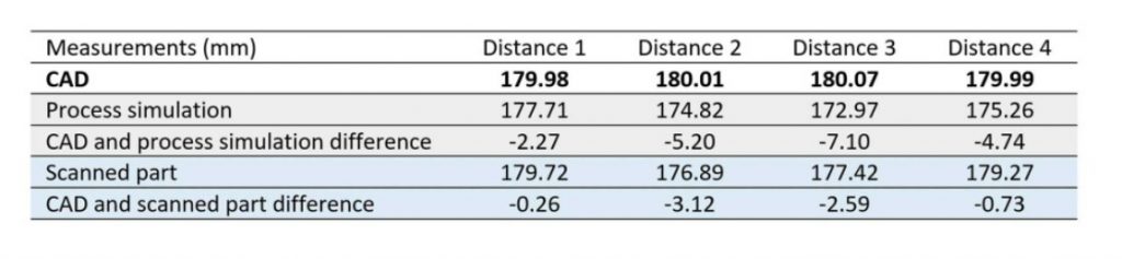
Table 1 –Distance measured in scanning, in the original CAD and in simulation.
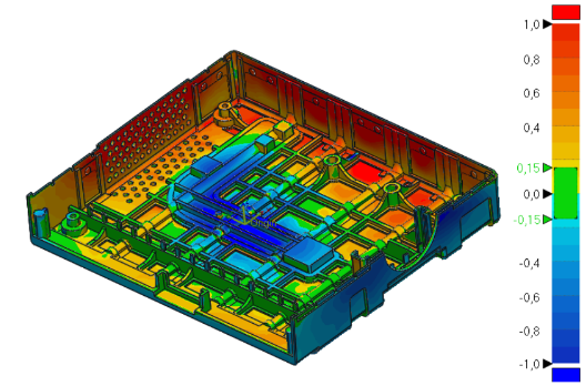
Figure 3 – Colour mapping de uma versão inicial do produto.
Case study 2 – Digitalisation for monitoring MAIT-Manufacturing, Assembly, Integration and Test – Application in Composite Materials
Composite materials are widely used in high-performance thermomechanical components and structures, and their application in critical components and structures is common. Therefore, it is crucial to closely monitor the operational lifespan of these structures while in service, in addition to maintaining strict control over their processing conditions. This detailed monitoring is essential to ensure structural integrity and optimized performance over time. By carefully recording and analyzing the critical variables associated with ongoing operations, it is possible to identify patterns, anticipate wear, and implement proactive corrective measures. The versatility of composite materials and their production techniques increases the potential for applying different sensing methodologies, enabling application contexts not replicable with other materials and/or production processes. The incorporation of sensing systems during the production process represents an innovative approach that enables the production of intrinsically composite components with sensors integrated into their structure, capable of monitoring a wide range of physical variables relevant to product performance and quality. This allows for real-time and continuous information and monitoring of components throughout the Production, Assembly, Integration, and Testing (MAIT) phases. This new approach to continuous component and process monitoring is highly disruptive, and composite materials offer a broad field of application for this comprehensive monitoring concept.
PIEP has been applying optical sensing techniques, with a special focus on the insertion of FBG sensor networks into composite laminates. This methodology, as previously mentioned, allows monitoring of the different phases of the product life cycle: from manufacturing to use monitoring, using the same sensor network. Figure 4b) shows the optical fiber configuration embedded in the composite laminate that allowed monitoring of the resin front (see Figure 5), resulting from the vacuum-assisted thermoset resin infusion (VARI) process. Subsequently, after the part has cured, and using the same sensor network, the impact energy is evaluated by monitoring deformation transients, as shown in Figure 6.
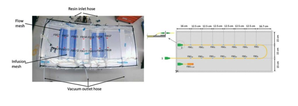
Figure 4 – In a) vacuum-assisted resin infusion process and indication of the positioning of the FBG sensors (14), b) diagram of the layout of the FBG sensor network.
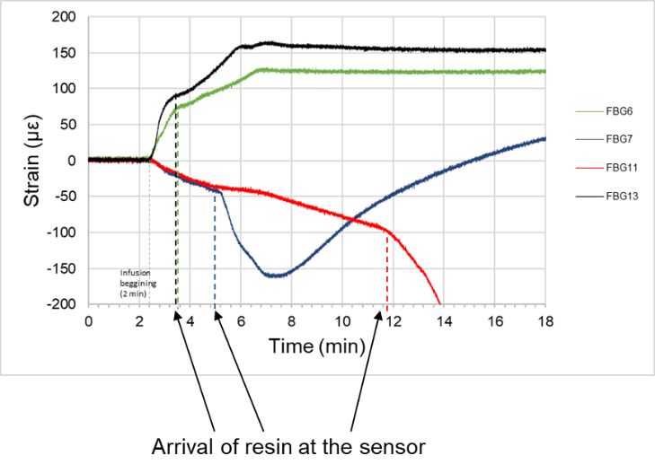
Figure 5 – Resin front monitoring, through deformation monitoring by onboard optical sensing.
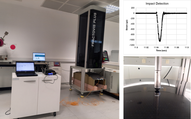
Figure 6 – Impact monitoring, by monitoring transient deformation, through on-board optical sensing. In a) impact testing machine (dart drop) and optical signal acquisition system; b) deformation transient generated by impact stress; c) impactor and sensorized composite plate.
Critical components are emerging as an area with high potential for the application of advanced scanning techniques. Scanning these components allows for accurate and comprehensive analysis of their geometry, structure, and functional performance. In this field, PIEP has applied optical sensing to COPVs for hydrogen gas storage (6). In this application, the optical fiber is embedded during the filament winding process, which allows: 1) monitoring of compaction stresses during the production process; 2) monitoring of deformation cycles during cyclic pressurization tests (see example in Figure 7); and; 3) detection and localization of impacts by monitoring deformation transients and residual deformation.
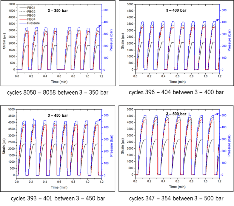
Figure 7 – Monitoring of cyclic pressurization tests (4 amplitudes), through on-board optical sensing.
Case study 3 – Data analysis and decision support – Application in the context of laboratory tests
With the emergence of Industries 4.0 and 5.0, data and its management, interpretation, and use have become a huge asset for companies, whether for internal consumption, with the digitization and sensing of equipment and digital monitoring through Digital Twins (7), or for external consumption, with the use of big data to create generative artificial intelligence models such as chatgpt or Gemini.
This digitization for internal consumption, as is the case study example, often involves the adaptation, digitalisation, and updating of legacy equipment and software. This entire process has its idiosyncrasies and difficulties that often overlap with other equipment and software. From what has been observed, this process is dynamic and flexible enough to be applied to a variety of different cases.
In our case study, there was an internal need to produce software capable of receiving, storing, altering, and comparing data from the analysis of the chemical and structural composition of internally synthesized polymeric biocompounds, which, due to their specificities, are not available in the available software.
The software has two main capabilities: 1) it feeds a database with Fourier Transform Infrared Spectroscopy (FTIR) analyses (an example of this analysis is shown in the graph in Figure 8), Thermogravimetry (TGA), and Differential Scanning Calorimetry (DSC). It also allows for data and spectra processing before storing them in an external database, allowing access to the centralized database from any device. 2) it supports the identification of the different polymeric compounds to be analyzed using the stored data that serves as the basis for this identification. To this end, several classification methods are being considered, such as Correlation Coefficient, Cosine Similarity, Euclidean Distance, Dynamic Time Wrapping (DTW), Spectral Angle Mapper (SAM), and Wavelet Transform. More recently, some Machine Learning algorithms can also be implemented to complement the results, giving them greater robustness and credibility.
In short, the development of a customized solution capable of centralizing, storing, and interpreting physical characterization data of materials, such as the one described in this case study, is of vital importance for increasing the efficiency and effectiveness of data management and interpretation processes, more specifically, in a laboratory context.
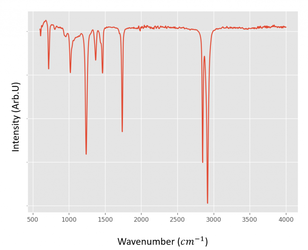
Figure 8 – Example of FTIR spectrum taken from a laboratory sample imported into the developed database.
Authors:
Agnieszka Rocha, Cátia Araújo, Carlos Ribeiro, Filipa Carneiro, Hugo Gomes, Paulo Antunes, Pedro Gomes, Sílvia Cruz, PIEP
Article originally published in InterPLAST magazine.

